Rework Technology: IR vs. Convection Air
Posted 2 Sep 2024 15:22 | 3,484 views
Competitor technology varies, but generally IR Technology refers to the top heat, bottom heat, or heat from both top and bottom. The key to understanding IR is to know its positives and negatives, how they affect each IR system, and how each manufacturer addresses them on their machine differently
TYPES OF IR
- Red Light Beam - usually low in power and used in smaller wattage lamps
- Ceramic Emitter Elements - high in power for large wattage per heater
- Quartz Lamp Rod - bright, yellow light and is an older technology (black IR rods)
- Hot Plate - style of heating with air circulating over or through the heater for higher power
EMISSIVITY
The transfer rate of heating with IR is commonly referred to as Emissivity. This is how efficiently an object absorbs and emits radiated energy, in this case heat. In other words, it is the rate that heat is absorbed into a material from an IR emitter.
Black components are most efficient for radiated heating. They absorb and emit thermal radiation very well; therefore, they have very high emissivities. If heat is transmitted into a black material, it heats up faster than a lighter color material such as white or silver lidded BGA, but it also cools down faster. Black to Black surfaces have the best heat transfer rate. Each material (component) can have different rates of absorption due to surface and color of the part.
Components with silver, or a dye, on top of the BGA will have a less effective heating for the same power applied to the ceramic heater. The loss of efficiency is because some heat is reflected off the surface instead of being absorbed. This means the solder under the reflective surfaces will be at different temperatures than that under black components (see Figure 1). Therefore, if components are a different color, even if they are the same size, different heating profiles will need to be generated.
The assumption applied in both cases is that the power and height of the emitters are the same for both the black and reflective components.
With convection heating, the same profile will work on black parts, silver part, or parts with reflective dyes on the top because they are not absorbing radiated heat, so emissivity is not a factor.
Figure 1. Reflective Dye on a BGA
WHY IS CONVECTION HEATING IS THE PREFFERED TECHNOLOGY FOR REFLOW OVENS?
- Convection heating technology is a more equal heating method, with smaller Δt (delta t, temperature difference) across many devices on a PCB.
- Temperature across the complete PCB is more accurate and responsive to typically less responsive component sizes.
- The older IR style ovens were manufactured approximately from 1996 -2008.
- Silver surfaces have a lower emissivity, so when heated by IR they will not absorb radiated heat as well as black surfaces. This is not a problem with convection heating.
- Ceramic emitters, which are the most well-known types of IR emitters, will efficiently transfer heat into silver pads because they are higher power, but they will also heat black plastic connectors to higher temperatures more quickly. Because of this, the Δt’s for ceramic emitters are not ideal compared to convection.
RED LIGHT IR
Red light is generated through a zoom camera-type lens creating a red dot. The size of the red light is condensed or expanded to alter the size of the heating area like zoom on a camera lens. The red light needs to be focused differently on parts of different heights, much like the focus on a camera lens. If it is not focused, the heating will not be efficient and will be diffused. Components of different heights (i.e. BGA, CSP, CBGA, CCGA) will require different focus positions.
Red Light IR responds quickly to the “on/off” heating cycle but is not a powerful method of heat transfer. The lamp and lens assembly (150 to 200 watts) can have a short life. The life of the bulb is directly dependent upon the hours of use.
As the lamp/heater surface changes color from heating, the effectiveness of radiated heat can change, and heating profiles may need to be adjusted to compensate for the deterioration of the lamp. Also, adjacent component heating is unavoidable with the use of a round red beam on square components. Other adjacent parts are heated not just square BGA (see Figures 2 and 3 below).
Figure 2. Top Red Light, PDR Figure 3. Bottom Red Light, Martin Red Light Preheater
IMPORTANT WHEN CONSIDERING REWORK TECHNICAL HEATING INFORMATION
In lead-free rework, the pre-heater should be the most power part of the heating process. This prevents overheating the components with high temperature heat on top of the part. Simply put, less heat from bottom (pre-heater) means more heat needed from top, and this is not a good solution. More heat used on a BGA from the top heater will increase warpage of the BGA, causing solder bridges in the corners as they are the weakest point. Corners generally become the hotter locations because there is less mass. This becomes even more of an issue with thin BGA components.
When IR technology is used as a pre-heater from underneath (Figure 3), the reflow temperatures must be accomplished from the top heater because the pre-heater is not strong enough. The top nozzle will need to use a different technology, usually convection technology, as seen in the Martin Red Light Preheater (Figure 3).
When Top Red-Light heating is used, a slower ramp rate is achieved, and the IR light must be controlled to heat the required area. This then means the underside heater must to do all the work. So, care must be taken to not melt the underside of the PCB during the heating process with this technology during the peak reflow zones. Black plastic connectors are particularly sensitive to IR on the bottom of a PCB and can melt or be damaged warped easily.
CERAMIC HEATER EMITTER TECHNOLOGY
Ceramic Heater Emitters, as previously mentioned, are the most well-known type of IR emitter. They can vary in color (e.g. white, yellow and black) depending on the manufacturers. They consume more power and are quicker to ramp up in temperature. This is controlled at a high element surface temperature, about 460⁰C (860⁰F), until they achieve a radiated temperature from emitter of 230⁰C (450⁰F) at the PCB level.
CERAMIC EMITTER VS. CONVECTION HEAT
Convection air temperature is the temperature of the air at the surface of the PCB or component part. No estimates need to be made from the source temperature to the surface temperature of the PCB; they are the same for convection heaters, unlike IR ceramic heaters. Source temperature refers to the temperature of the heating element surface, while surface temperature refers to the temperature hitting the PCB surface, not the PCB temperature itself. This difference between source and surface temperatures is a common issue in IR reflow ovens and makes profiling difficult when reflowing PCBs.
Power generated from ceramic emitters ranges from 500W to 1000W. This allows rework machines to ramp up quickly, but they then take time to cool down.
The angle of radiation emitted from these heaters is dependent on the shape and angles of the emitter surface. This angle can be difficult to control in array rework systems for the smaller sized BGA locations (e.g. 25mm by 25mm). This then makes it difficult to achieve equal temperatures with top ceramic IR heaters for components in small locations, or if parts had shinny dyes or reflective surfaces.
Figure 4. Ceramic Type Emitter Designs
The radiation, as seen in Figure 4, is emitted at a 90º angle from the surface of the emitter. Different shaped emitters can radiate at wide or smaller angles. Unfocused radiated IR heat can be effective in heating up, but not in cooling down.
Figure 5. Ceramic Heating Elements
CERAMIC HEATER TECHNOLOGY WAS USED IN THE FIRST SMT REFLOW OVENS ABOUT 20 YEARS AGO
Ceramic heater technology is used in many competitor rework machines. These heaters are common in older IR reflow ovens and are now used by some as top heaters, bottom heaters, or both. These style heaters are not easily focused for local heating on the top of the component since the radiation is not an exact square or rectangle. Because of this irregular shape, adjacent parts are exposed to high temperatures (see Figure 5). Often tin foil is places on plastic components to prevent them from melting.
Figure 6: Tin Foil on Adjacent Parts for Ceramic IR Heating
In lower end machines, the shape of a square is simulated by adjustable square shutters, much like a nozzle on a convection rework machine. The main difference is that the square shutter is not as close to the component being reworked as the convection nozzle. This is another cause for adjacent components to be unnecessarily heated. This is not a problem with convection nozzles because they are placed directly over the desired component.
Ceramic heaters are quick to heat up because they use a lot of power, but they are slow to cool down from ambient air because they are high mass heaters. Hence, this technology cannot cool the PCB quickly if it is still in the heater location. Some machines show the PCB being moved away from the heat, but this is a bad idea when the component being reworked is still within liquidous melting temperatures.
QUARTZ HEATERS (AN OLDER STYLE)
Quartz heaters were used in the first IR ovens, were a very bright white light, and used a lot of power compared to hot air ovens. These heaters are fast to respond and need to be close to the PCB to be effective. They can draw a lot of power per inch compared to other IR heaters, typically 100W per liner inch (e.g. a 10-inch tube is 1000W).
With five or six tubes running, the process is costly and requires a three-phase power supply. Considering the amount of power consumption, the heat transfer is not efficient. It is difficult to focus heat because the light is not focused with either a beam or a lens assembly. They could be of good use in a pre-heater, but they produce scattered heat and cannot be focused in any one area. Average life of heater tube is 5000 hrs.
Figure 7. Quartz Heater Rod
CONVECTION HEATERS
Convection Heaters are generally low mass and can be heated up quickly. With the power off and the airflow remaining on, the heat is dissipated from the element quickly making the cool-down cycle short. The higher the mass of the heating element, the longer the time required to get cold ambient air to the PCB. The cold air is blown onto part (reflow nozzle) and/or underside of PCB (preheater) during cooling process. The air must be controlled and the temperature reading method must be stable, resulting in rather nice, quick heat ramp-up and cool-down processes.
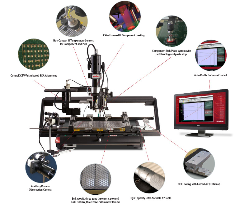
Due to the low mass of the heating element (Figure 7), element wire temperature does not overshoot the desired temperature and reacts quickly to temperature needs. The closer the preheater is to the PCB, the less heat is required and is more efficient. This was incorporated in the new design of the APR Scorpion product range to bring the preheater closer to be more efficient and require less time to heat the parts to rework temperatures. Also, a dual preheater is talked about later in this application note.
These heaters can respond quickly, even to a lower temperature. This is important for lead free solder profiling because the last zone, known as the hold or flat zone, is generally at a lower temperature than the ramp zone. Another benefit of convection is that the heating chambers can be used to cool PCBs without moving it off the board holder, particularly with dual preheaters which are on all APR Products.
Figure 8. APR Open Coil Convection Heaters
Notice that in the element shown in Figure 7 (left) the wire is the heating element area and can be heated-up or cooled-down quickly due to its low mass. Air is the transport medium for the heat. If the airflow is increased, and the heater can maintain temperature, the ramp rate can be increased with no increase in source (wire) temperature.
An important consideration with Convection Heaters is that, when profiling, if the source temperature remains the same and the airflow is increased the transfer ramp rate is increased. For example, the ramp rate into the PCB or components is faster with more airflow, but the temperature is not increased. This is not the case in any of the IR radiated heat transfer methods; the temperature must be raised to heat faster.
DUAL CONVECTION PRE-HEATING ZONES
In some cases, different temperatures may be required by a pre-heater. The easiest way to achieve these different temperatures is to have multiple heaters on the bottom being controlled in variable times to change the air temperature.
Figure 9. Dual convection Pre-Heaters
Multiple pre-heaters allow for different temperatures from both heating zones, flexibility in temperature, and gives local heating under the rework area. This is advantageous for lead free or lead profiles to get a hotter spot under the rework part, stop the whole PCB from getting too hot and warping, and causing underside components to be reflowed and potentially drop off the bottom of PCB. The dual convection heater is a key feature and easy-to-use.
Figure 10. Green Dots = Small (Inner) Pre-heater; Blue Dots = Large (Outer) Pre-heater
CONCLUSION
To apply this study to rework, it is important to understand that in rework the PCB is static. In other words, it does not move during the reflow process unlike a reflow oven. In reflow ovens the PCB moves through already stable zones that are heated by air instead. This caters to the varying different PCB sizes and loads. Air is used in reflow ovens today because it is a more flexible and repeatable process than the older IR ovens. On the other hand, in rework, the zones must change temperature as the PCB stays still. The final zone (after reflowing) must be at the correct temperature and then PCB must be cooled to a safe temperature.
Rework machines must respond quickly and must not overshoot desired temperatures. The IPC Specification for body temperature of a BGA during rework is typically 260⁰C maximum, some are 250°C, which means that most of the power must come from the pre-heater. If not, the top heater will exceed the necessary temperature on the component part due to trying to drive the heating through the part from the top to melt the solder on the bottom of the BGA or other components.
The top heater was the one that had all the power in past rework machine designs because temperatures where not considered important. Simply removing the part and replacing it was the only concern. With lead-free solder, the reverse is just as important. The PCB must be cooled efficiently after a short time above reflow, between 60-90 seconds above 217°C with a peak of 235-245°C. The time above reflow must also be controlled. So, we can see the difference between maximum component temperature of 260°C and the solder temperature. The process window is small and needs to be repeatable and controlled every time a profile is ran. If the time to cool varies, then the time above reflow temperature is extended.
So, by cooling from underside with inner and outer convection heaters the process is completely repeatable and can maintain the same time above melting (217°C) liquidous temperatures. Most lead-free reflow specifications are looking for 5°C repeatability in any time zone with no more than a 10 second reflow time variances. When considering lead-free rework, it is easy to see that the temperatures are higher, and the time above reflow is shorter. These factors are not new, but the older technology (IR) is not easily applied to this specification with higher repeatability within a given rework process.